Completed dual-op machining and automation cell with robot, conveyors, and fenced safety envelope.

Case Study | Off-Highway Driveline Manufacturing

Time Study to Lights-Out: Fixture-Led Cell Design That Scales

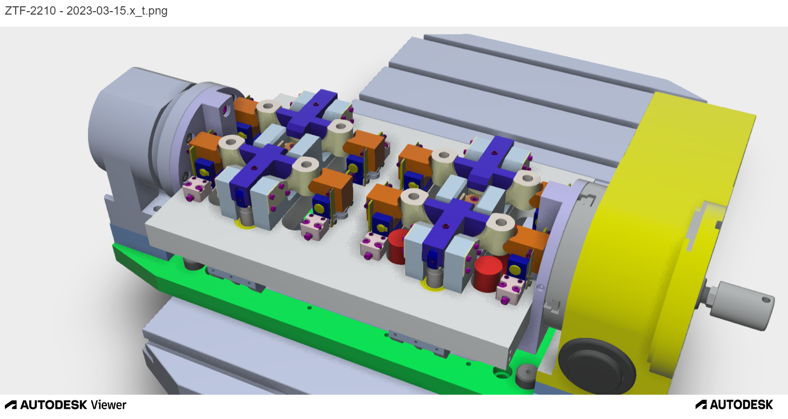
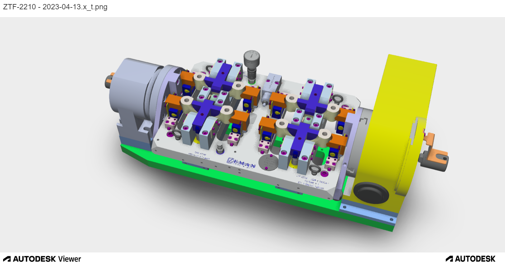
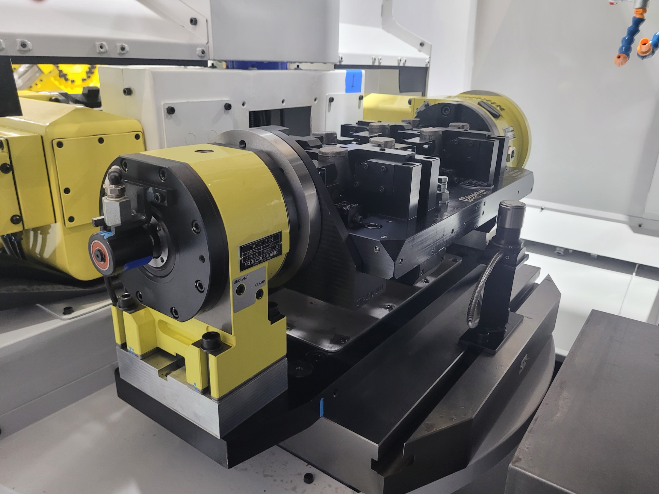
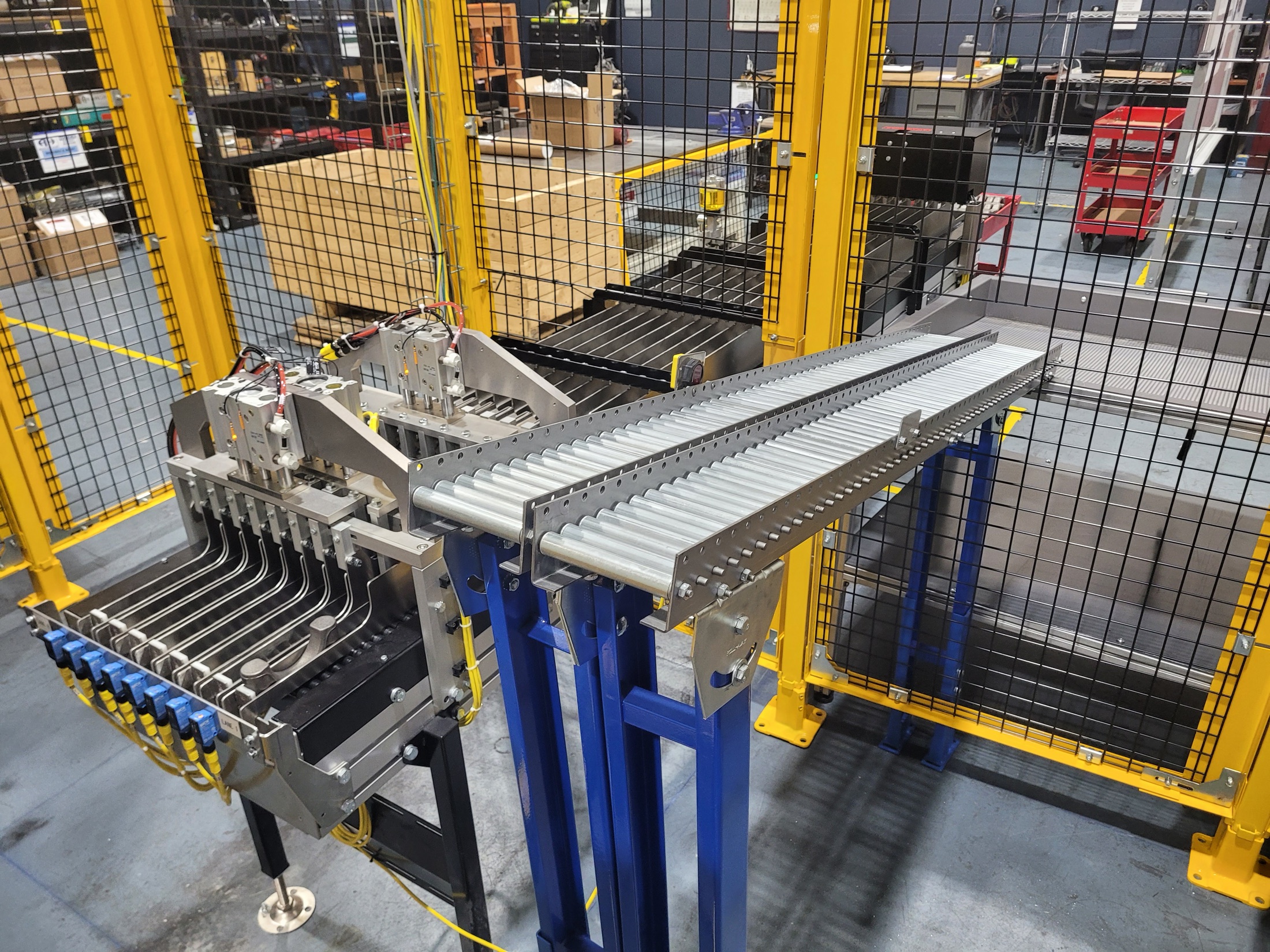
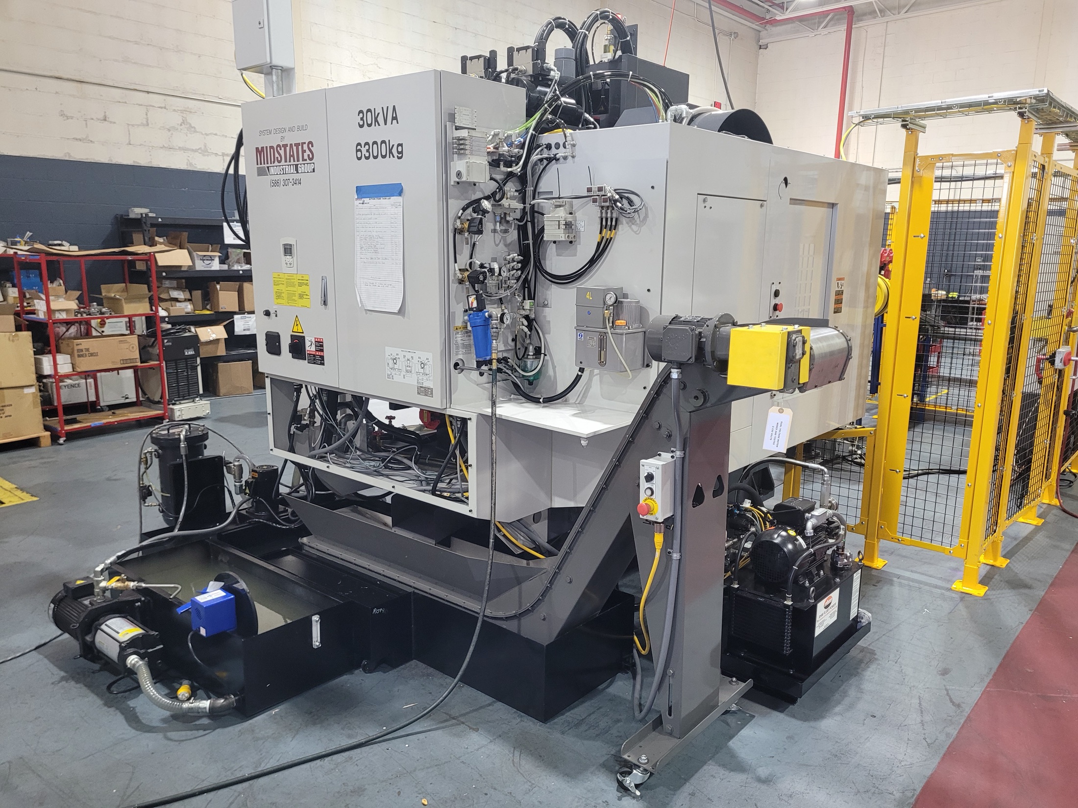
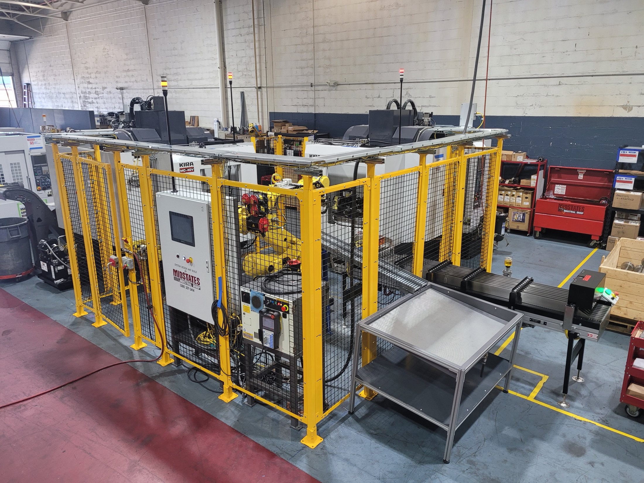
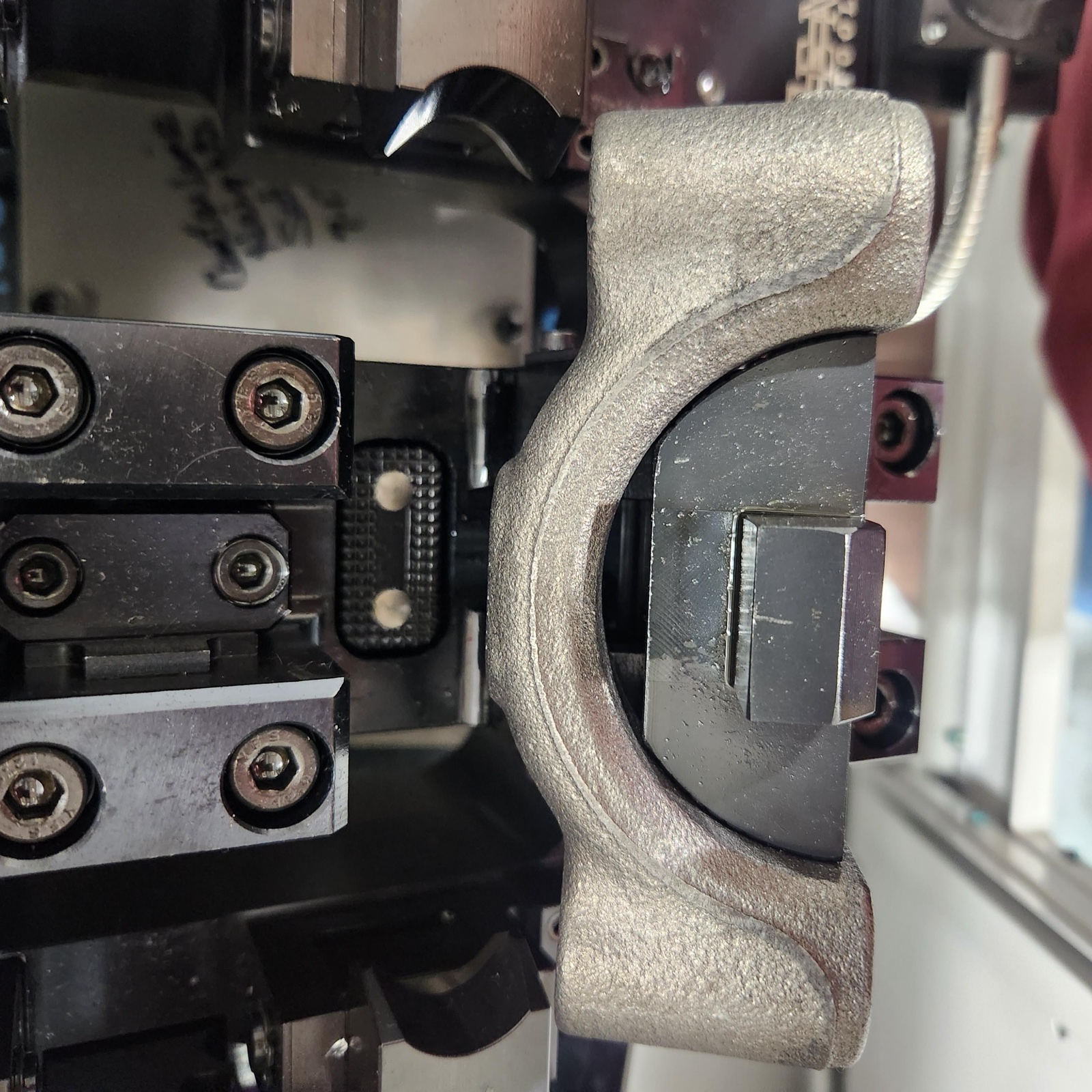
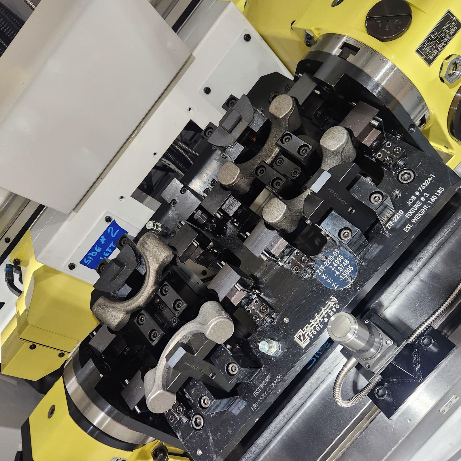
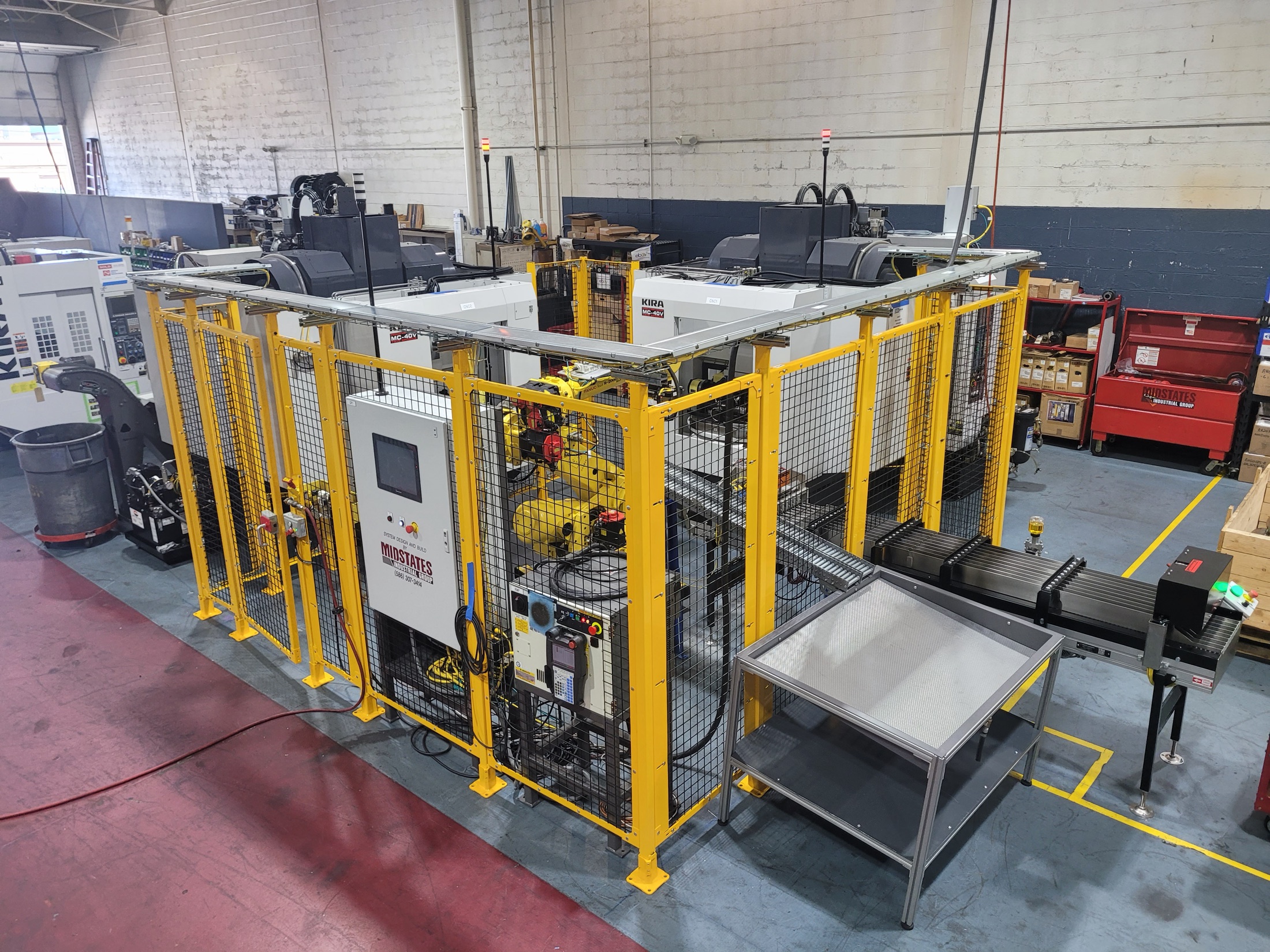
A North American off-highway driveline supplier needed a high-volume machining cell that could hit quota and stay stable through launch changes. Midstates used comparative time-study data, then built the final architecture around one decision: a dual-op look-through rotary fixture that enabled both machining and automation strategy.

Annual Requirement

1.8M parts/year quota support

Efficiency Plan

92% planned line efficiency

Machining Model

Dual-op machining per machine

Delivery Mode

Full turnkey multi-machine cell

Capability Tags

automation robotics EOAT design fixture design rotary fixture look-through fixture dual-op machining multi-machine cell conveyance lights-out manufacturing turnkey

Story Arc

Step 01

Time Study

Single-op and dual-op process paths were modeled side-by-side with cycle-level detail before equipment architecture was locked.

Step 02

Cell Design

The rotary look-through fixture became the center of gravity for machine selection, EOAT layout, and conveyor handoff logic.

Step 03

Implementation

Midstates delivered the full cell and absorbed late engineering changes without forcing a reset on launch readiness.

1) Time Study: Two Paths, One Decision

Why compare options first?

This program had throughput pressure and part-family variation risk. Early architecture mistakes would have multiplied machine count and handling complexity later. Time studies were used to evaluate throughput, balancing, and scalability before design freeze.

What the analysis asked

  • Can one strategy reliably support the annual quota profile?
  • Which architecture scales better as feature and geometry variation increases?
  • How much machine count and transfer complexity can be avoided?

Option A: Single-Op Route

Internal study model: 6 parts/cycle, 142.2-second net cycle, 23.7 sec/part baseline.

  • Strong for simpler part families and straight-through sequencing.
  • Higher risk of additional dedicated operation banks as variation grows.
  • More transfer points between operations in larger line configurations.

Option B: Dual-Op Route (Selected)

Internal OP10/OP20 studies included a 90.4-second 4-part case (22.6 sec/part) and broader part-family scenarios.

  • Supports OP10 and OP20 inside each machine architecture.
  • Reduced projected machine count versus separate op-dedicated banks in planning models.
  • Lowered expected floor-space and handoff burden while preserving throughput intent.

Selection Logic

The dual-op strategy won because it kept cycle potential competitive while improving scalability and reducing system complexity. That decision directly set up the fixture, automation, and implementation approach that followed.

Single-op fixture concept used in early process studies.
Single-op concept from early process exploration.
Dual-op fixture concept showing revised architecture used in planning.
Dual-op concept that informed the selected architecture.

2) Cell Design: Fixture First, Everything Else Follows

The core idea

The look-through rotary fixture was not an accessory to the machine choice. It was the reason the final machine and automation topology worked. Fixture visibility, clearance, and part presentation drove robot access strategy, EOAT geometry, and in/out conveyance alignment.

What the fixture architecture enabled

  • Dual-op part handling logic within a twin-spindle palletized environment.
  • Robot-friendly pick/place windows and repeatable part orientation control.
  • Cleaner integration between machining sequence and conveyorized flow.
Rotary fixture assembly inside machine envelope for dual-op machining.
Dual-op rotary fixture architecture in-machine.
EOAT and load-rail detail used for automated part feed integration.
EOAT and load-rail interface.
Conveyor to fixture handoff area for automated cell flow.
Conveyance handoff geometry.
Twin-spindle machine installed in final automation cell.
Twin-spindle machine integration.
Completed cell overview showing machine, fencing, and conveyance.
Final integrated cell layout.

3) Implementation: Delivered, Then Adapted in Flight

Live cell operation during integration and launch-phase refinement.

Midstates delivered a turnkey multi-machine cell and continued tuning through implementation. Instead of treating late ECRs as rework events, controls and handling logic were structured for controlled adaptation. That protected launch momentum while preserving core throughput objectives.

Single-Spindle Continuity Mode

The full cell was programmed to continue production if one spindle side became temporarily unavailable.

Fixture/EOAT Hang-Up Mitigation

Handling logic and fixture interaction details were revised to reduce hang-up and double-part risks during launch.

Conveyance and Safety Updates

Conveyor and safety revisions were integrated during commissioning without abandoning the original delivery path.

Close-up showing fixture interaction point used to diagnose hang-up condition.
Close-up diagnostic view used during hang-up mitigation.
Fixture condition showing double-part hang-up scenario during implementation.
Double-part condition addressed through launch-phase updates.

Program Outcomes

Quota Alignment

Designed to support a 1.8M parts/year requirement profile

Efficiency Target

92% planned operating efficiency for the production model

Machining Structure

Dual-op sequencing inside each machine architecture

Implementation Result

Turnkey delivery that stayed flexible through multiple ECR events

Why this case matters

This project worked because time study, fixture engineering, machine architecture, and automation were solved as one system. The result was not just a faster cycle model. It was a cell architecture designed to stay productive when real-world changes arrived.

Request Similar Application Review